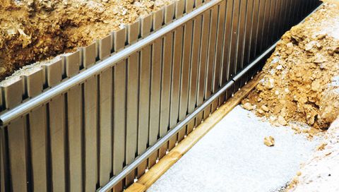
Foundation Formwork Systems

Technical specifications type FS 2001 G:
| Element length with overlapping: | 3.1 m |
| Element length actual: | 3.05 m |
| Element height: | According to specifications |
| Profiling of lateral wall: | smooth interior |
| Push-in brackets: | ø 10 mm |
| Recommendation for bracket distance: | approx. 50 cm |
| System components: | 3 (Casing + bracket + angle plate) |
| Weight per sqm: | approx. 14 kg |
| Free-standing cement height: | to 1 m |
| Available in radius: | upon request |
| Available with base plate laying: | no |
Delivery time per casing: | by arrangement |
| Assembly times: | approx. 0.1 h/qm |
Multiply reusable foundation wall shuttering with smooth inner sides type FS 2001 G
System specifications type FS 2001 G:
The MSL FS 2001 G system is an innovative development of the FS 2001 system.
The FS 2001 G system consists of only 3 components:
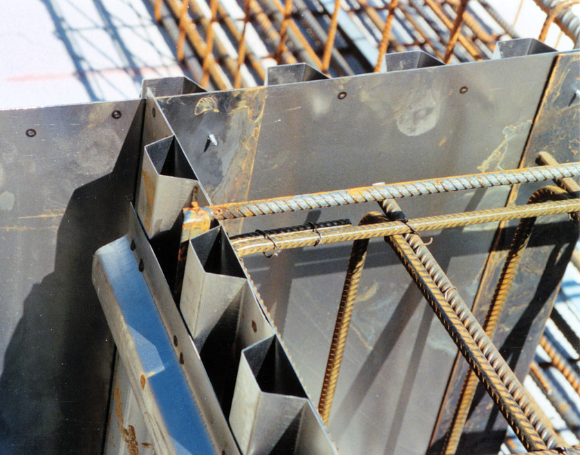
- trapezoidally profiled interior and exterior foundation walls (of identical design)
- upper and lower gapping means (of identical design)
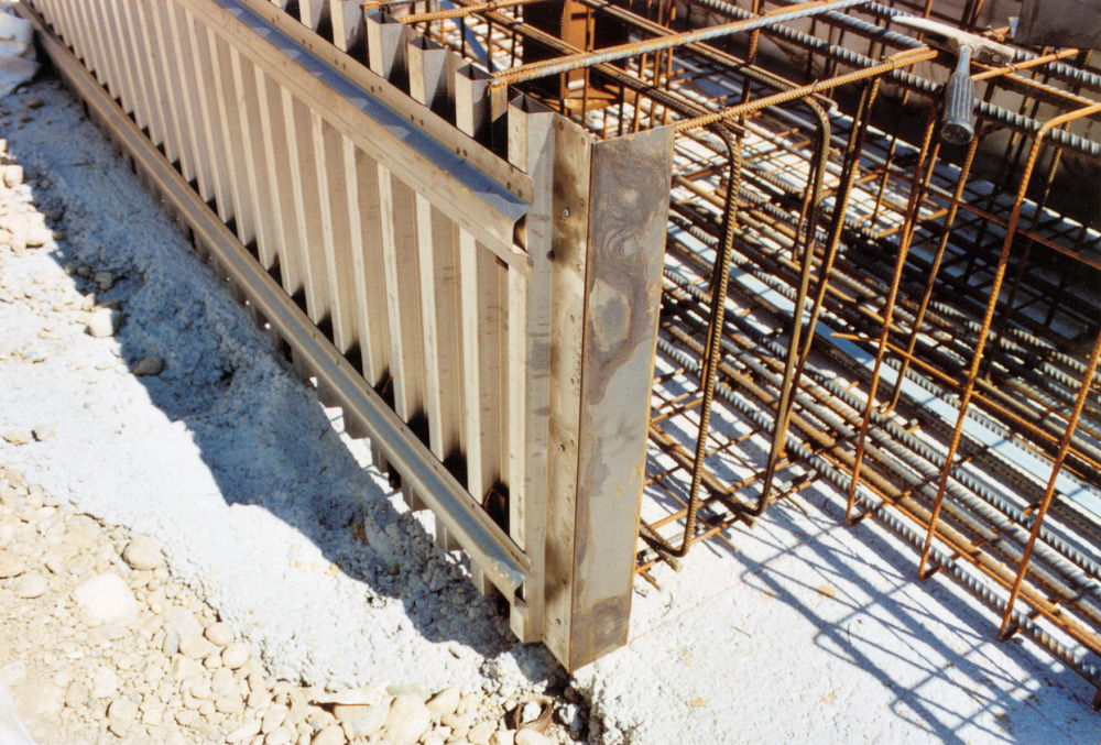
- angle brackets as connecting elements for shaped
- parts such as interior and exterior corners
By contrast with the well-proven type FS 2001 the FS 2001 G has a smooth inner side.
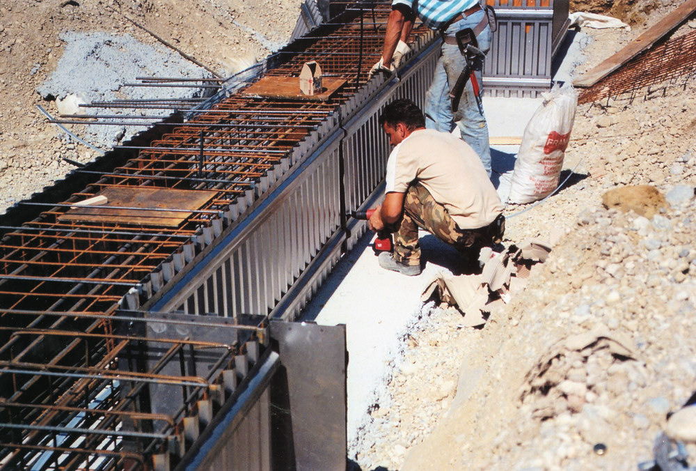
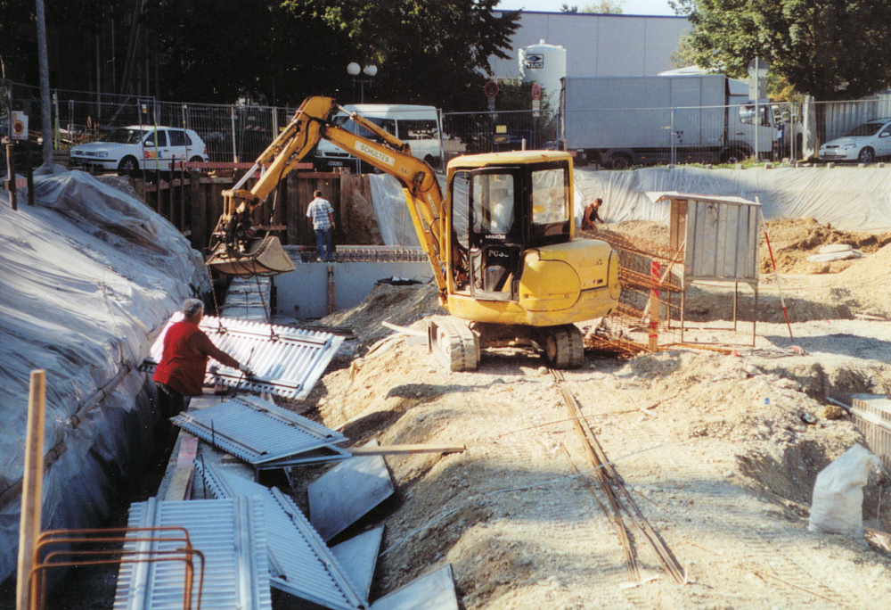
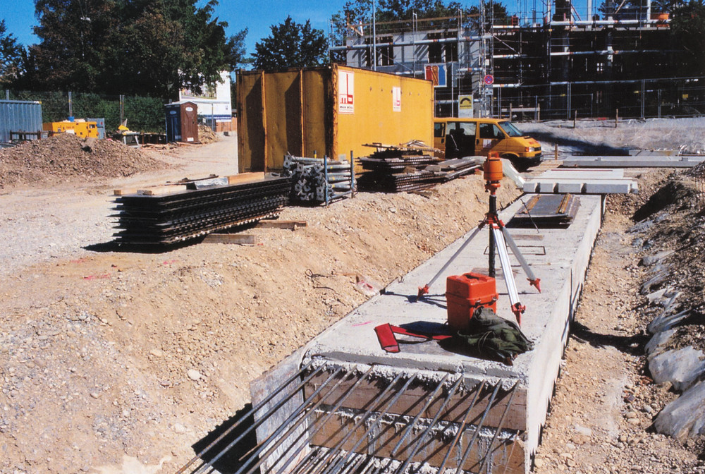
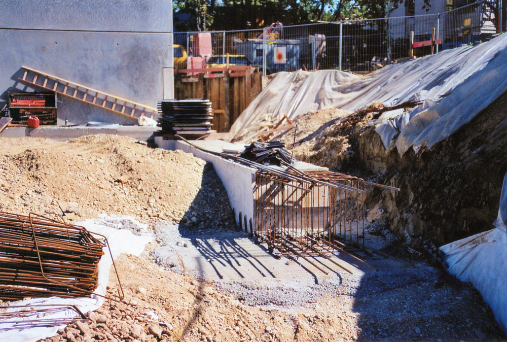
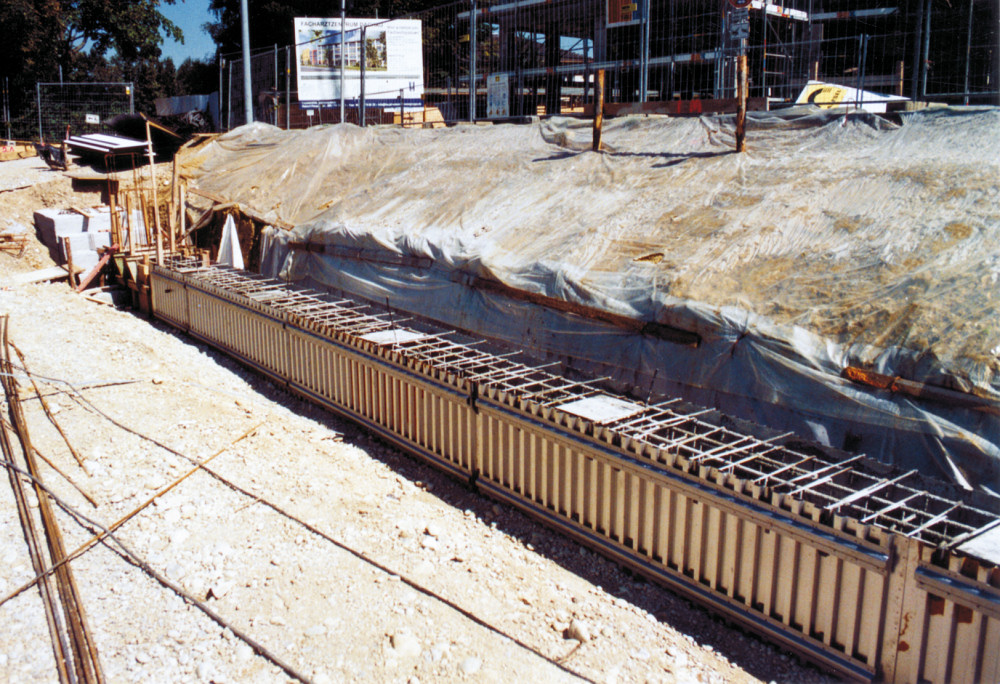
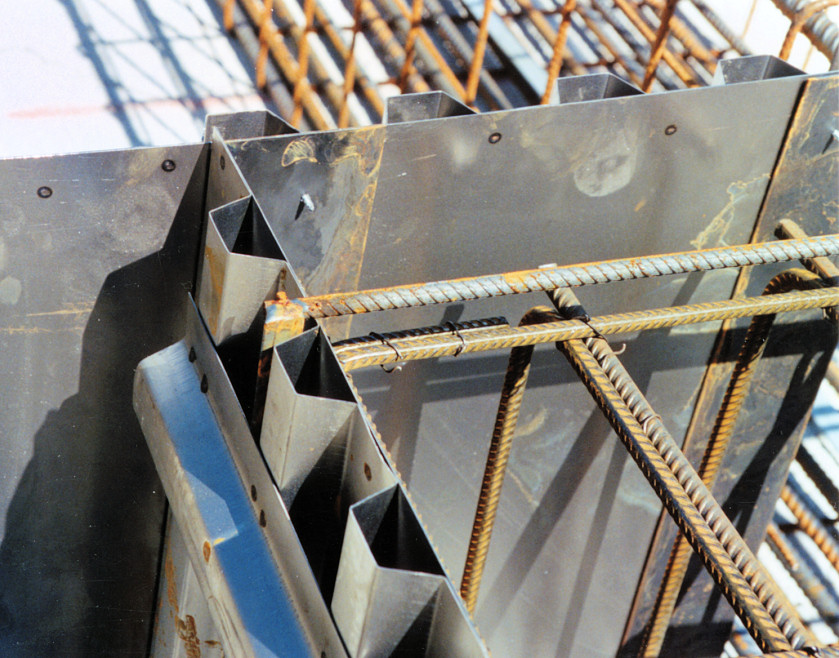
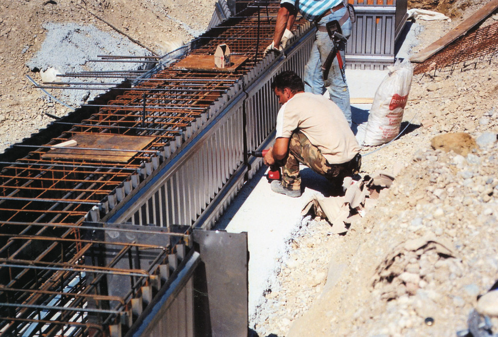
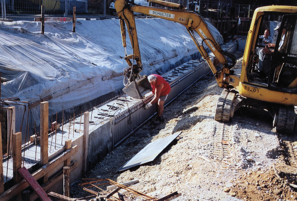
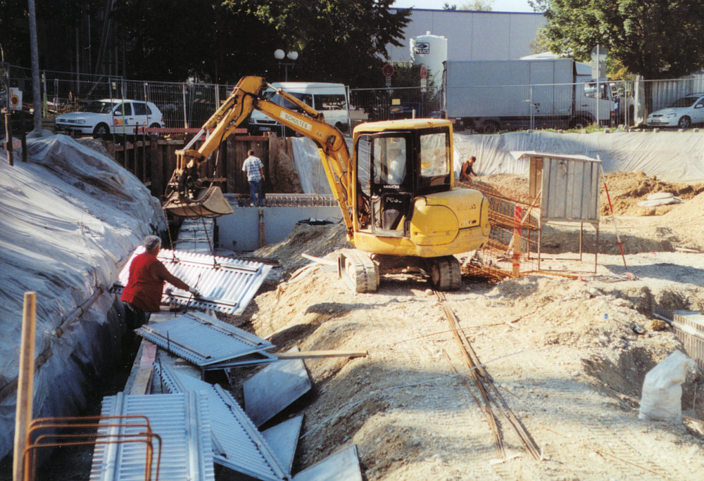
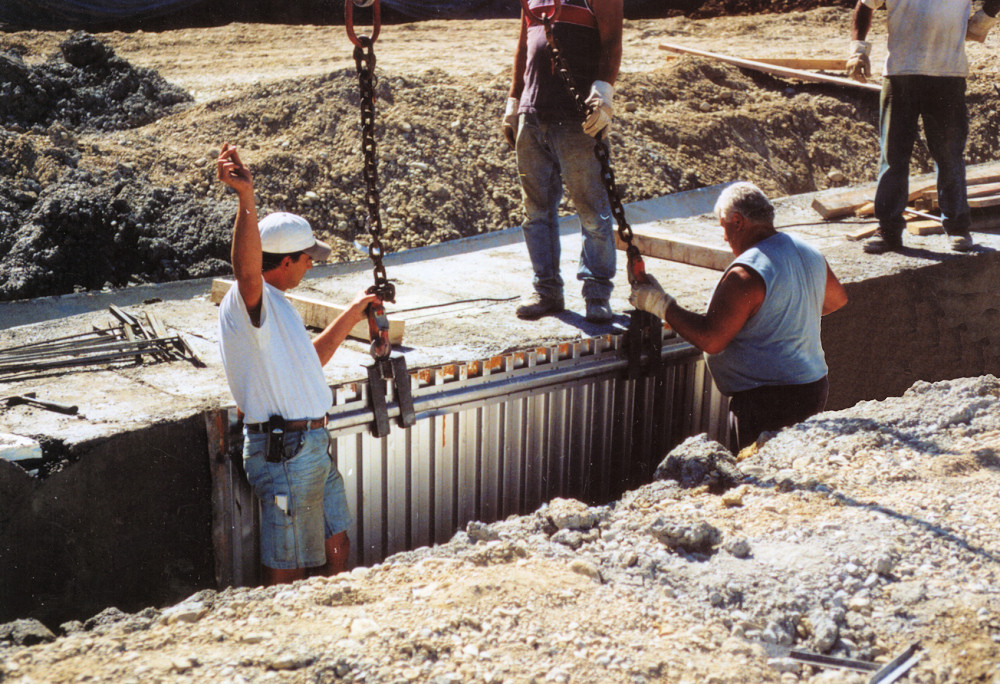
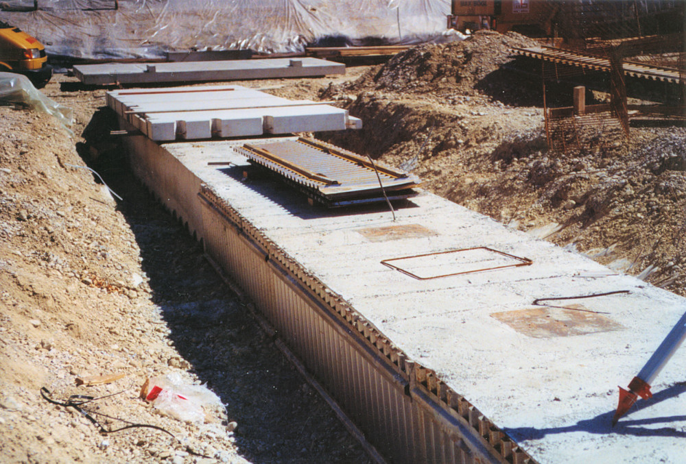
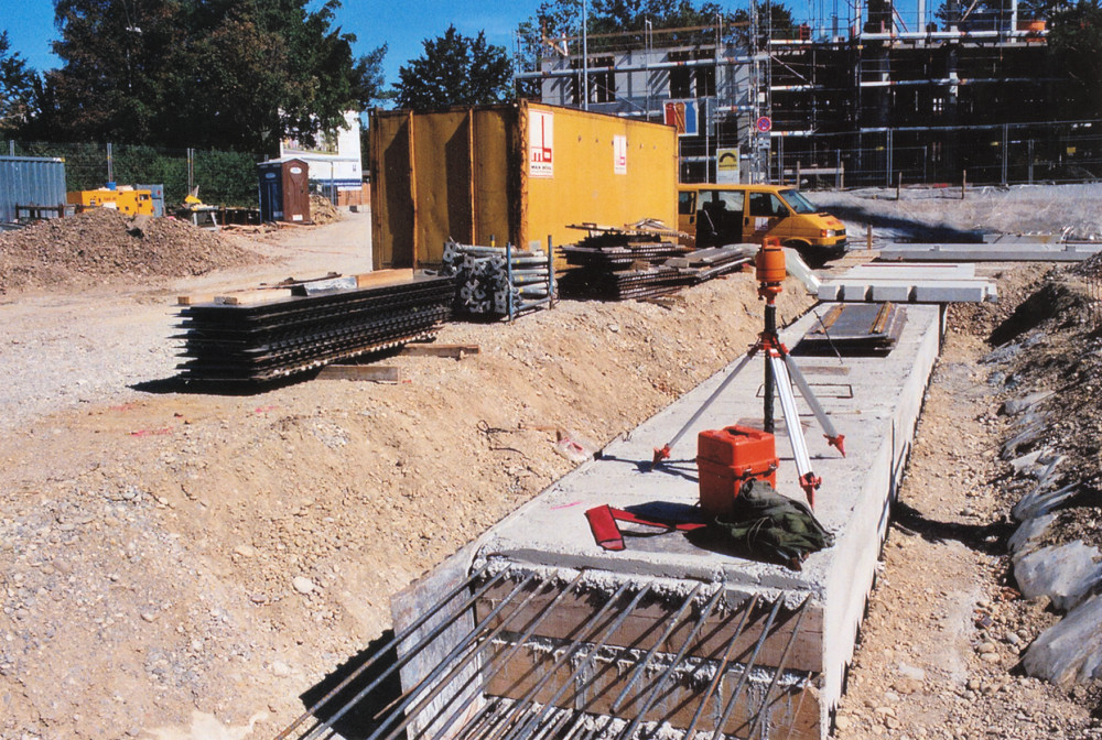
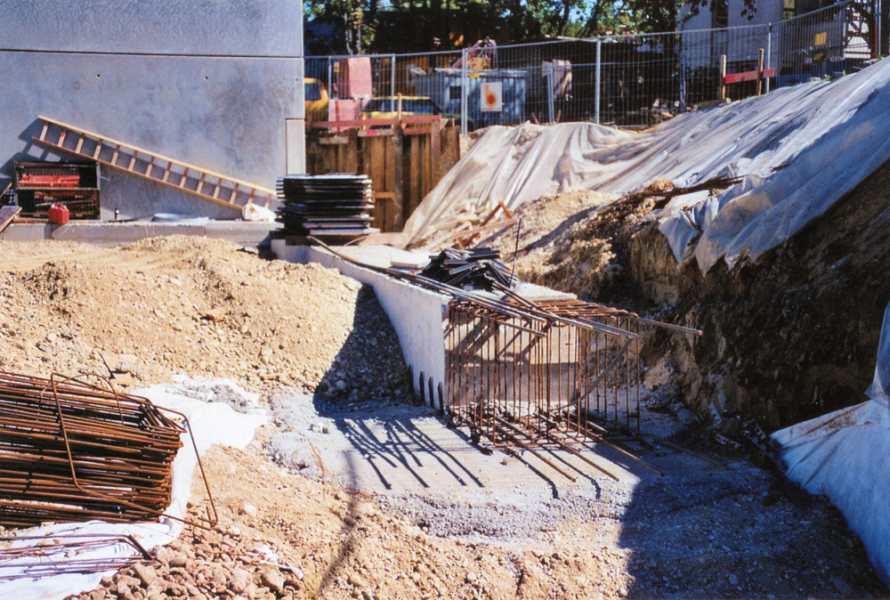
This has the advantage that the shuttering can be removed from the foundations and multiply reused once the concrete has set. Furthermore, this saves concrete by comparison with profiled foundation walls as there is no concrete loss due to the profile. Once the shuttering has been removed the foundation wall can easily be insulated and/or damp proofed. This design allows you to build up reinforcement before installing the shuttering (see photo 9). Shaped parts as in photo 12 are created using the brackets supplied (photos 10 & 11). Self-tapping screws are used to join the brackets with the shuttering. We recommend that shuttering overlaps be fastened together using self-tapping screws. The overlaps should always be secured top and bottom with separators as shown in photos 4 to 6.
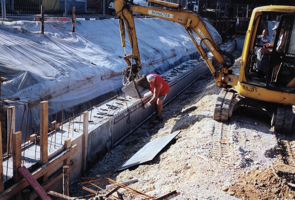
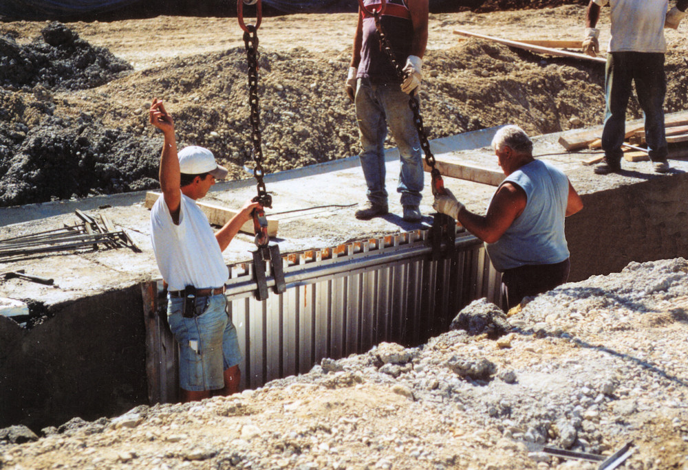
Once the concrete has set the upper separators are removed from the foundation shuttering. The shuttering walls are then separated from the foundations and pulled off upwards through the upper separators (see photos 13 to 15).
Photos 16-18 show various foundation sections with the shuttering wholly or partially removed. The mounting device in photo 15 can be loaned from MSL.
The photos show of a construction project in Dachau. Shuttering elements 0.8 to 1.2 meters high were used. Each element was used up to 4 times.
We recommend this type for major building projects involving foundations made in sections. Please refer to the table and the building recommendation for further technical details.


